Models
Making  your own models is by far the best way to understand biotensegrity but is often dismissed as being a rather trivial exercise. They do, however, provide tangible connections to the words and make the whole thing real. Models reveal important aspects that can otherwise seem rather abstract and will make the basic principles come ‘alive’.
Cranial vault as tensegrity
A discussion among tensegriphiles revealed that there are a myriad different materials and methods of putting them together and the following are some of the things that I have tried. Computers can be good at exploring different aspects of tensegrity,Burkhardt, Kanno Connelly particularly when animated, but often fall down when they start to describe biology in terms of equations. A couple that I can recommend are those produced by Gerald de Jong and Jean-Claude Guimberteau.
Essentially the only things needed are compression struts, tension cables and a means of holding them together but as you will see things can get a bit more complicated when building the more exotic types. Here are some links for models and more ideas: Kenneth Snelson; Tom Flemons; Marcello Pars; Tensegrity wiki; Pugh; Kenner; Artefact Pro; Tensegri-Teach; Pretenst
 There is no standard method of naming tensegrity structures at the present time because sculptors, mathematicians and biologists take different approaches and use different terminology (see definitions page); even these pages may have some inconsistencies as things move on and get refined.
MODEL MAKING
Simple table top and hand size models are fairly straight forward particularly if using light wooden dowels and non-stretchable cord. Daniele-Claude Martin and Susan Lowell de Solórzano have both made simple-to-follow videos that describe how to make them.
It has been noted that large metal struts of several feet in length can be extremely dangerous during their construction, particularly when securing the last one that is the most likely to spring out during final assembly, so wear protective gear if you are making these monsters. You can watch the assembly of a large 6-strut tensegrity made by Shalom Nachshon.
Note that the descriptions may not coincide precisely with their related pictures because of differences in the way that small and large-sized screens configure them – it is called ‘progress’ apparently.
T3-PRISM
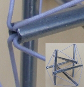
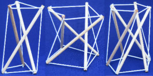
 The T3-prism appears to be the simplest model to build with just three struts and nine cables, and Juris Sils also gives a nice demonstration of how to build it, but from a practical and biotensegrity perspective it is actually much more complicated than the T-icosa. The struts can be made from wooden dowels with a notch at each end to secure the cables, or alternatively, tubes with the cables threaded through and secured at the ends with a wooden or plastic plug and superglue (cyano-acrylate). The best material that I have used so far is 3 – 6 mm wooden dowel (craft suppliers or BBQ/kebab sticks) and 1 mm polyester cord (jewellery suppliers).
 A single cut is made at each end with a band saw or carborundum grinding disc that comes with the small model tools such as the ‘Dremel’ (I set the disc up on a lathe), the cord stretched so that it can be passed into the cut and a drop of superglue applied when finished.
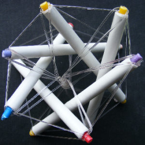
T-ICOSAHEDRON or T-ICOSA
The T-icosahedron is definitely the best model for demonstrating the properties of tensegrity – balanced tension and compression, discontinuous compression, geodesic geometry, close-packing, minimal-energy, chirality, modularity heterarchies, elasticity, auxetic behaviour etc, and has loads of potential. It also relates to the icosahedron as the finite element of biological structure, hence its name, although its name is often disputed by non-biologists (see Definitions page). A single T-icosa can be made using the method described by Daniele-Claude Martin and Susan Lowell de Solórzano or by holding all the struts in one hand and running a single piece of cord over the ends in the correct sequence: this latter is fiddly but quicker, and soon comes with practice. I also demonstrate another method in workshops that uses six strings but there are no pictures as yet.
 The icosahedron has ‘cubic’ symmetry, so in this case there are three groups (relate to 3-D) with two parallel struts in each group, and the pattern of links between strut ends is the same in each case. Apart from this it is as well to forget about cubes because they connect to the limitations of conventional man-made structures, and biotensegrity has far greater potential.
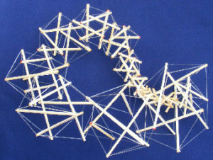
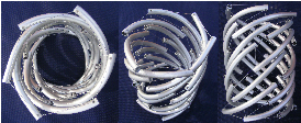
CHAINS OF T-ICOSA
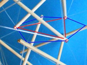
 The above model of the T-icosa chain was made with elastic bands with the cord run over the strut ends to link them all together, the elastic bands carefully cut and removed, and the cord secured with superglue (cyano-acrylate).
I have now superseded the original method of making chains (by fixing the struts around and along a wooden dowel or plastic pipe) by constructing individual T-icosa (above), and then connecting 3 struts (which form a left-handed helix on one model) with 3 struts that form a right-handed arrangement on the other model, because it is simpler and neater overall. It might help to mark one end of the three strut groups as one colour (red), then superglue all the nodes (strut ends) except these three; when set, turn it over and attach the three red nodes into the centres of the cables from a triangle on the other model (blue) and superglue them, then cut away the three cables that form the ‘tension-triangle’ (red) to leave a tensioned hexagon (blue). The new model uses relatively less material and is thus structurally and energetically more efficient – just like biology!
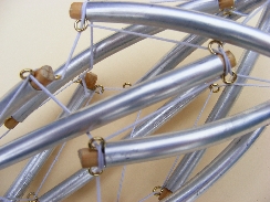
 Some of my earlier models used plastic or metal tube with the cord running down the tube length, or across the end through two holes, or through eyes screwed into the ends of wooden dowels. The cord running down the length of small tubes is secured with toothpicks/plastic rod and super-glue. Larger tubes have the cord running between two holes at the end, and secured with a matchstick and super-glue.
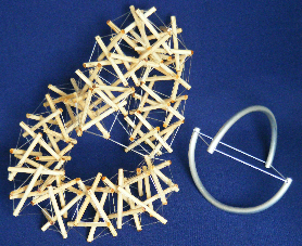
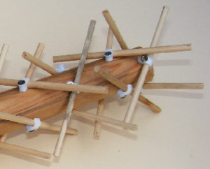
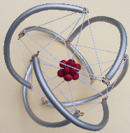
CURVED STRUTS
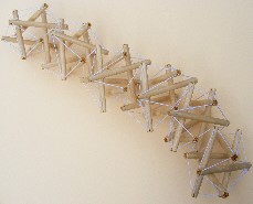
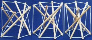
 Curved struts are useful for modelling curved structures but should always be considered as representing higher levels of complex heterarchies in biology. These models are generally made from curved chains of T-icosa, although the cables and struts within them are all straight, but you will also seem some curved tubes that are simplifications of these T-icosa chains. The picture that contains both the two curved T-icosa chains and curved metal tubes are essentially the same but showing how complex biological curves can be simplified for modelling purposes.
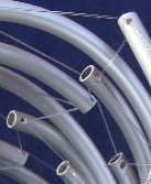
Note that curved struts need lateral support because they will otherwise flop about. My early models used a piece of wooden dowel glued into the ends with small eye hooks on either side for attaching the cords that stabilize it; but it is much neater to drill small holes on either side near the ends for the cords – plus finish with a drop of glue on the inside to bind the cords as they cross between the holes.
When stringing up, one strut needs to be fixed to something firm so that the other struts dangle below as you are working. This is much more fiddly than straight struts so use toothpicks or the point ends of BBQ sticks to lock the strings into their holes during the process. I always use a preset sequence for the 6-strut models.
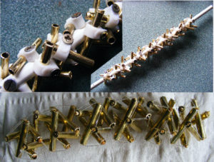
 JIGS
JIGS
Eventually, a model can become so complicated or fiddly that it may be necessary to hold all the struts in place while stringing it together. Here are pictures of the jigs used to make small T-icosa chains with struts secured to a rod or large tube with cable clips. The 1 mm cord passes over the end of each strut (or through the tube) which means going up and down the whole structure several times with the configuration of each node being the same. If you find that something has been missed at the end, just go back to a point where there was an option about which direction to take, and try the alternative. When finished, secure the ends with a wood/plastic plug (tube) and superglue, undo the screws and it is finished.
 The same principle applied to the more complicated helixes,
which used a 4″ drainpipe as a jig, with the centres of the strut tubes fixed with cable clips screwed into the plastic and the whole thing cabled up. In this case, place sturdy washers beneath the clips in order to hold the struts more firmly.
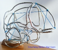
THE CRANIAL VAULT MODEL
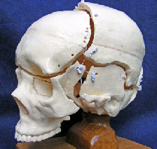 The skull model obviously has curved plates of bone and the tensioned cables represent the dural mater membrane lining the inner surface of the bones.
The cranial vault page has more details of the connections but if you want to copy this the most important thing to get right is that the cables connect the convexities of adjacent bones and the holes are as close as possible to the edges.
The wire model of the cranial vault (top) copies the outlines of the bones and makes it easier to see what is happening inside.
Have fun making these and contact me if you have any problems, alternative solutions and ideas.
TENSEGRITY ENERGETICS – the following is really a musing and exploration of the biotensegrity model to see where it might lead.
So far these pages have shown how tensegrity heterarchies and curved geometries contribute to making structural and energetic sense of complex patterns and shapes, while still relating to the basic geodesic, close-packing and minimal-energy principles. The models can be relatively static structures and it may sometimes be difficult to visualize how they can move or change shape (a section on the ‘jitterbug’ will be added soon).
 Both Snelson and Fuller emphasized that tensegrity cables and struts are the “physical representations of invisible forces” and as Kenner noted:
“…equilibrium is not a static condition of being ‘at rest’, but rather the resolution of forces that are pulling in different directions…” Kenner 2003, p 13. Living tissues are dynamic structures and are changing all the time with nothing remaining truly static for more than a few milliseconds at most.
This section is an attempt to connect all the platonic solids with the energetics of tensegrity structures without using heavy mathematics; it is really a work in progress and something to think about. The geodesic and definition pages describe how curved struts link curvature with heterarchies; and the simple 3-strut tensegrity model is a useful starting point.
According to the formula: angle of twist = 90o – 180o/n where n equals the number of struts. Thus the T3-prism has a twist of 30o between the upper and lower triangular ends and the vertical/diagonal cable connects the ‘top’ node of one strut to the ‘bottom’ node of the next strut along.
 The T4-prism is connected similarly with the ends having a twist of 45o. Re-configuring it so that the diagonal cable connects to the bottom node of the second strut (around the axis) causes the twist to double (2 x 45o) and the strut centres to pass through the middle of each other; the nodes now correspond to the vertices of an oblong but curved-struts become necessary if the struts are to remain separate.
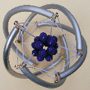
A T5-prism has 10 nodes so it cannot correspond directly with the 20 vertices of a dodecahedron but it may be that the curved-struts can allow something else to happen (haven’t worked out what yet); the model shows a dodecahedron suspended in the centre.
 A T6-prism has a twist of 60o, and re-configuring it so that the diagonal cable connects to the bottom of the third strut causes a double twist (2 x 60o); moving the diagonal to the fourth strut (3 x 60o) causes all the struts to touch each other in the middle. Another model with looser cables suggested that the struts might just be able to remain separated but getting the right balance of cable length and tension has so far proved too difficult to confirm this.
This series of T-prisms may reveal something about the dynamics of biotensegrities, ie where the basic forces of attraction and repulsion act spontaneously. Each T-prism was able to show something different, such as moving the diagonal or using curved struts, which suggests that going back through the series to a 2-strut tensegrity might also be interesting.
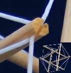
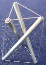
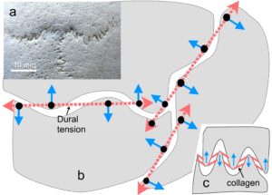
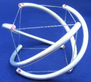
Starting with the four spheres (eg. atoms) that go to make up a tetrahedron (a), the forces of attraction (tension) between their centres act in straight lines and pull them together (dotted), while the outer surfaces of the spheres keep their centres apart (repulsion) and form a compressed octahedron (yellow). 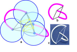 Remember that the octahedron emerged when the tetrahedron was increased to a higher order, or frequency (geodesic page), which means they are related to each other and in this instance are representations of tension and compressional forces. Straight and curved lines are also related to each other, and repulsion is represented here by just two curved-struts that hold their centres of mass apart (red); removal of the spheres now causes contraction of the tensioned tetrahedron into a square within a 2-curved-strut tensegrity (b,c).
The curved-struts compare with the ‘X’ tensegrities modelled by Snelson where each straight strut passes through the centre of the other.
Regressing through this series to a one-curved-strut tensegrity will produce an archers bow,Connelly; Motro and reducing the curve to a straight line brings the strut coincident with the tension cable with both vectors balanced in 1-dimension.Fuller;
To put these shapes in context, a 1-curved-strut tensegrity reduces to a straight line with tension and compression balanced in 1-dimension; a 2-curved-strut ‘tetrahedral’ tensegrity reduces to a square in 2-dimensions; the nodes of the 3-strut (T3-prism) almost correspond with the vertices of an octahedron, and this is the first structure in the series to be stable in 3-dimensions; and the four strut (T4-prism) can be reconfigured with curved struts such that it corresponds to a cube. (Leave aside the T5-prism and dodecahedron for now).
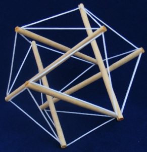
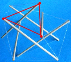
 If the struts of the T6-prism could be rotated through 90o on different axes and moved around with extra cables added they would probably form a T-icosa (I think!). This structure is a balance between two T3-prisms of opposite chirality and because each one has a twist is probably why the nodes only approximate with the vertices of an icosahedron.
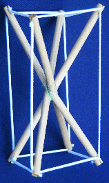
Consider this example of a helical compression strut emerging from the interactions of tension cables. This T6-prism is stable with just four cables at the ends of each strut. In addition, other cables connect the top ends to the bottom ends of opposite struts by winding around each other through the centre of the structure. They thus produce a central helical strut that can resist some axial compression out of just tension cables.
Lots to work on!